Goal
Once again we'll hack the PS1 here.
This time it will be about the power supply.
Once again we'll hack the PS1 here.
This time it will be about the power supply.
DISCLAMER: Working with the power supply means working with 110V/220V. There's no need to modify the high voltage part of the power supply but keep in mind that touching it while it being plugged in or shortly after being unplugged can kill you. Don't do this hack if you're not an electrical engineer. You are on your own. I'm not responsible for anything that can be caused for trying this hack.
My problem is that I don't want to move to power off or reset the console.
The actual button pushing will be electrically done by a Raspberry Pi.
The actual button pushing will be electrically done by a Raspberry Pi.
The most known way to turn on and off a switch is using a relay. Those are mechanical stuff that will die slowly, make noise while changing state and be big, among others.
Hopefully solid-state relays were invented and have no moving parts.
https://en.m.wikipedia.org/wiki/Solid-state_relay
Hopefully solid-state relays were invented and have no moving parts.
https://en.m.wikipedia.org/wiki/Solid-state_relay
I only have electromechanical relays though so I used them.
[Source code: https://github.com/electrojack/psxvx]
Inputs and outputs
In order to correctly simulate normal usage, the RPi must know whether the Reset button is pressed and whether the Power button is activated.
This gives 2 inputs.
It must also simulate Reset button (put LOW on one GPIO) and control one relay for 3.5V and another one for 8V.
The two relays will be controlled by the same GPIO.
That makes 2 outputs.
Reading inputs
The Reset button blocks connections between GND and the Reset signal.
In order to read the Reset status we measure the voltage of the left button pins: 0V means Reset is pressed, 3.5V means released.
The Reset button blocks connections between GND and the Reset signal.
In order to read the Reset status we measure the voltage of the left button pins: 0V means Reset is pressed, 3.5V means released.
The Power button controls both the 3.5V and the 8V lines.
This means the Power button being pressed would give 3.5V at the left of the button, and 0V if released.
This means the Power button being pressed would give 3.5V at the left of the button, and 0V if released.
Controlling power output
As discussed above, we need two relays (3.5V and 8V).
Also we need to cut the traces right after the buttons.
The relays have to connect the power sources and the power connector.
They will be controlled with a GPIO, using the same script than in Part II (software video switch) with another GPIO port.
As discussed above, we need two relays (3.5V and 8V).
Also we need to cut the traces right after the buttons.
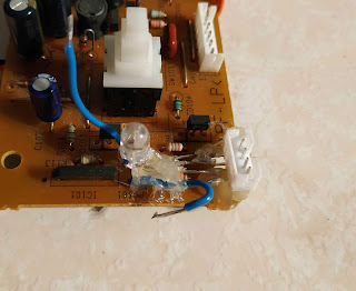
In this photo, I replaced the relays with jumpers
They will be controlled with a GPIO, using the same script than in Part II (software video switch) with another GPIO port.
Controlling reset output
If the RPi is dead I don't want the Reset signal to be sent, which means I'd want the corresponding GPIO not to be put LOW.
For this reason I'll use an NPN transistor.
Once again we'll use the GPIO controlling script.
If the RPi is dead I don't want the Reset signal to be sent, which means I'd want the corresponding GPIO not to be put LOW.
For this reason I'll use an NPN transistor.
Once again we'll use the GPIO controlling script.
Making it smart
The last thing to do is making a script reading the Reset and Power states and controlling the outputs based on these.
It is not done yet but it is coming.
The last thing to do is making a script reading the Reset and Power states and controlling the outputs based on these.
It is not done yet but it is coming.


