Thursday, February 21, 2019

Modding my PS1 - Power supply hacking (Part III)

Goal
Once again we'll hack the PS1 here.
This time it will be about the power supply.

DISCLAMER: Working with the power supply means working with 110V/220V. There's no need to modify the high voltage part of the power supply but keep in mind that touching it while it being plugged in or shortly after being unplugged can kill you. Don't do this hack if you're not an electrical engineer. You are on your own. I'm not responsible for anything that can be caused for trying this hack.

My problem is that I don't want to move to power off or reset the console.
The actual button pushing will be electrically done by a Raspberry Pi.
The most known way to turn on and off a switch is using a relay. Those are mechanical stuff that will die slowly, make noise while changing state and be big, among others.
Hopefully solid-state relays were invented and have no moving parts.
https://en.m.wikipedia.org/wiki/Solid-state_relay
I only have electromechanical relays though so I used them.


Inputs and outputs
In order to correctly simulate normal usage, the RPi must know whether the Reset button is pressed and whether the Power button is activated.
This gives 2 inputs.
It must also simulate Reset button (put LOW on one GPIO) and control one relay for 3.5V and another one for 8V.
The two relays will be controlled by the same GPIO.
That makes 2 outputs.

Reading inputs
The Reset button blocks connections between GND and the Reset signal.
In order to read the Reset status we measure the voltage of the left button pins: 0V means Reset is pressed, 3.5V means released.
The Power button controls both the 3.5V and the 8V lines.
This means the Power button being pressed would give 3.5V at the left of the button, and 0V if released.

Controlling power output
As discussed above, we need two relays (3.5V and 8V).
Also we need to cut the traces right after the buttons.


In this photo, I replaced the relays with jumpers


The relays have to connect the power sources and the power connector.
They will be controlled with a GPIO, using the same script than in Part II (software video switch) with another GPIO port.

Controlling reset output
If the RPi is dead I don't want the Reset signal to be sent, which means I'd want the corresponding GPIO not to be put LOW.
For this reason I'll use an NPN transistor.
Once again we'll use the GPIO controlling script.

Making it smart
The last thing to do is making a script reading the Reset and Power states and controlling the outputs based on these.
It is not done yet but it is coming.


Modding my PS1 - Power the Rasberry Pi from the PS1 power supply (PSX-VX Part V)

Goal
In this short article we'll power the RPi with the PS1 power supply.
Powering the RPi with an USB cable is ugly and defeats the purpose of a fully integrated system.

Stepping down from 8V
Unfortunately the supply only provides 3.5V and 8V.
We thus need to lower the voltage from 8V.
For this I use an LM2596 converter.

The principle is fairly simple:
  • PS1 power supply GND goes in IN-
  • PS1 power supply +8V goes in IN+
  • RPi GND goes to OUT-
  • RPi +5V goes to OUT+

LM2596 converter
Left: IN = PS1
Right: OUT = RPi

PS1 power supply: GND and +8V to connector
(Don't mind the 4 red and orange cables at the left)

Adjust OUT+
Before connecting the RPi, you must adjust the output voltage for it to be +5V (±5%).
This is easy: connect the +8V input to the PS1 power supply and put a voltmeter on the output.
Then turn the pot on the converter until the voltmeter shows +5V.

Power the RPi
The Pi can be powered through GPIOs, so OUT+ goes to the +5V GPIO (top right) and OUT- to one of the GND pins.
Everything should work now.

Sources

Modding my PS1 - RGB LED (PSX-VX Part IV)

As my PS1 receives more capabilities than initially thought by Sony, it needs a status LED showing more states than just ON/OFF.
For this reason I need to have more colors than just green.
I chose an RGB LED to replace the original LED.
It will be driven by a Raspberry Pi.


Deleting original LED
Getting rid of it is pretty quick.
Sadly its legs are bent so it's not practical but it will leave without too much work.

Placing the new LED
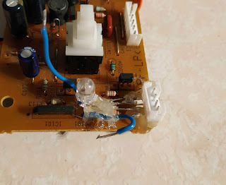
Hard rework of the traces is out of question so I left the whole LED with its legs above the board.
I bent them at around 100° to be able to solder something on it without touching something on the board.
I put a connector on the legs.
I kept the LED and the connector in place with some hot glue.

Controlling
Solder the VCC (or GND) and the 3 color legs (check if your LED is common anode or common cathode) to the RPi and choosing the color will be as easy as controlling 3 GPIO's.
The intensity of each color will be choosable using PWM.

Code
See the code at: https://github.com/electrojack/psxvx


Don't mind the two blue cables

Video
https://www.youtube.com/watch?v=XR9lDs6q3II

Saturday, February 2, 2019

Using arduino-cli

I missed the arrival of arduino-cli.
This is a great tool as we can finally use arduino libraries and codes without having to use the GUI, which I, personally, can't stand.

As usual my usage is different from the vast majority of people.
In this case I don't burn the bootloader so I can't use the upload functionality of arduino-cli.
Instead I use avrdude.

Everything stays easy though:

1. Follow the instructions here: https://github.com/arduino/arduino-cli


# 2. Install missing core (cf instructions)
nano .cli-config.yml           #add core: https://github.com/MCUdude/MiniCore
arduino-cli core update-index
# 2a. Look for your core
arduino-cli core list
# 2b. install it
arduino-cli core install MiniCore:avr

# 3. search for board name -> MiniCore:avr:328
arduino-cli board listall


# 4. Compile your project
arduino-cli compile --fqbn MiniCore:avr:328 myproject

# 5. Upload .hex file and fuses
sudo avrdude -p m328p -c linuxgpio -e -U flash:w:myproject.MiniCore.avr.328.hex \
       -U lfuse:w:0xe2:m -U hfuse:w:0xd9:m -U efuse:w:0xff:m


I had problems with avr-g++ and other binaries not being found.
I don't have the time to fix this nicely.

I edited ~/.arduino15/packages/MiniCore/hardware/avr/2.0.1/platform.txt


#change this:
#compiler.path={runtime.tools.avr-gcc.path}/bin/
#to this:
compiler.path=/usr/bin/   # or the directory where you have the avr-g++ binary
                          # you can use `whereis avr-g++`


Saturday, January 19, 2019

Modding my PS1 - Video switch (PSX-VX Part II)

Goal
In the second part of this PSX modding series, we'll focus on the video output.
The goal is to control the signal that is sent: instead of only the one from the PS1, I want to be able to switch it with another signal.
As always, you can find the source code here: https://github.com/electrojack/psxvx

PS1 video hardware
The video output is sent through the 12-pin proprietary AV MULTI OUT connector (that also sends sound signals).
There are actually three sent video signals through the cable: RGB, S-Video and composite.

In this article I'll work on the composite signal (https://en.wikipedia.org/wiki/Composite_video).
You can see the connector soldered on the board at the top right of the following picture, you can recognize it with its 2 rows of 6 pins.


Once again, info about the pins can be found in the PS1 bible.

  1      RGB-Video Green
  2      RGB-Video Red
  3      Supply +5.0V (eg. supply for external
           RF adaptor)
  4      RGB-Video Blue
  5      Supply Ground
  6      S-Video C (chrominance)
  7      Composite Video (yellow cinch)
  8      S-Video Y (luminance)        
  9      Audio Left      (white cinch)
  10     Audio Left Ground            
  11     Audio Right     (red cinch)  
  12     Audio Right Ground
  Shield Video Ground
            ____________________________
           | 12    10   8   6   4   2   |
           |    11    9   7   5   3   1 |
           |____________________________|

So my composite signal is pin 7.

Switcher circuit
Now I need a circuit whose output can be chosen by an input from two sources.
Fortunately, composite signals only have positive voltage so my circuit can be really simple.
There are special ICs to switch between video sources but I wanted to keep it simple: I made it with just 2N2222 transistors.


It only contains 3 resistors, 3 2N2222's and power supply (3.5V).

The next step is choosing the second source of video. I'll be using a Raspberry Pi for 2 additional reasons:
  • it can deliver 3.5V
  • it can drive the circuit through one of its GPIOs

Hardware work on RPi
My RPi is a Zero so it has no headers and the video output is done through the 'TV' pads.
All we have to do is soldering male pin headers (or wires) to 3.5V, GND (power supply), GPIO27 (driver) and TV out.

Hardware work on PS1
The composite video trace must be cut so the actual output is not sent to the video pin of the AV out port.
Then solder wires to AVOUT-pin7, actual video signal from the PS1 (follow the pin7 trace to find a blob to solder on) and video ground.

Wiring
RPI 3.5VSWITCH VCC
RPI GNDSWITCH GND
RPI GPIO 27SWITCH DRIVER
RPI TVOUT+SWITCH SOURCE 2
RPI TVOUT-PS1 VIDEO GND
PS1 AVOUT pin7 SWITCH OUTPUT
PS1 VIDEO SIGNALSWITCH SOURCE 1

Software work on RPi
Now we have to control the GPIO on the RPi.
I did it with a Python script.

import RPi.GPIO as GPIO
import sys
vidport = 27
GPIO.setwarnings(False)
GPIO.setmode(GPIO.BCM)
GPIO.setup(vidport, GPIO.OUT)
GPIO.output(vidport, sys.argv[1][0]!='f')

Save that as show_ps1.py and then you can run it with these commands:

python show_ps1.py true
python show_ps1.py false

Result
I'll add photos of the circuits later.
In the mean time here is a video of the actual result.

Saturday, December 22, 2018

Modding my PS1 - Memory card backup (PSX-VX Part 0)

I recently found my old PS1 memory cards and wondered how to retrieve the data on a computer.
This is the first article of a series on the original Playstation.
[Source code can be found here: https://github.com/electrojack/psxvx]

Step 1: Understanding the hardware
A memory card has 8 connections, all of them are linked to the corresponding ones of the controller in the same port.


(Data = grey, Command = purple, etc)

So there is VCC, GND, +7V (vibration).
The Acknowledge port is for the device to send an acknowledgement command after having received a byte.
Then Data (MISO), Command (MOSI), Attention (CS) and Clock (SCK) are standard SPI.

The rest of the info can be read there: https://problemkaputt.de/psx-spx.htm#controllerandmemorycardioports


Step 2: Software
As you can read in the PS1 Bible, talking to the memory card is pretty trivial.
Even better: Shendo created a program to flash to an AVR that talks to memory cards and a Python script that talks to this program.
That's what I used.

I adapted the .ino (C file to use with the Arduino software) program for the ATmega8535 I used for this task.
I also changed the Python script to better take errors into account.
I'll publish these in my PS1 software repo but in the mean time the Shendo's files works perfectly.

Step 3: Making it
I removed the controller/memcard block from the PS1 and soldered wires as in the first image.
MISO, MOSI, CS and SCK were connected to the ATmega8535 as expected, ATT is optional and was left alone and finally it looks like the +7V port can be connected to +3.3V without posing any problems (both with Sony memcards and third party memcards).
I used a Raspberry Pi to control the AVR chip (through RX/TX) but any UART computer would work.

And finally it's quite easy to make it work using the serial port to the chip.

$ python memcarduino.py  -p /dev/serial0 -r memcard.mcr                 
running mcduino check                                                   
passed mcduino check                                                    
Running mcr header check MCDINO                                         
Sending... \xa20001                                                     
Reading 129bytes...                                                     
passed header check                                                     
reading data from memory card...                                        
                                                                        
OK at frame 1/1024  Address:00 00 TimeTaken:0:00:00.225765              
OK at frame 2/1024  Address:00 01 TimeTaken:0:00:00.225847              
OK at frame 3/1024  Address:00 02 TimeTaken:0:00:00.225859              
...                                                                     
OK at frame 1024/1024 Address: 03 FF TimeTaken:0:00:00.225482           
SUCCESS                                                                 

Then you can use your *.mcr files as virtual memory cards in emulators and store them where you want.


Modding my PS1 - Chipping (PSX-VX Part I)

WHAT
[All the source code can be found here: https://github.com/electrojack/psxvx]
I recently decided to mod a PS1.
After a lot of research I found that the info about chipping was not easily understandable.
The reason is that there are many PS1 motherboards, several different modchips and scarce precise how-tos.

The different PS1 boards are here: https://en.wikipedia.org/wiki/PlayStation_models#Comparison_of_models
The one I bought is a PU-18.

Nearly everybody use PIC modchips but I have ATtiny chips so I used one: a ATtiny13 that was laying around.

If you read that you should know about the protection used in the PS1. If not, read this: https://twitter.com/foone/status/974277587764523010

Now the problem is: where and how should I inject the "SCEE" string?


WHERE
The SCEE string should replace the one actually read on the disk.
This string is sent on a Data line that is accessible on the back of the motherboard.
Also the actual output must be muted so that we can send the SCEE string without it being messed with with the actual data.
Fortunately this muting can be done by putting low a single accessible signal: the so-called Gate pin.


This image shows the back of a PU-18. (bottom left in this picture: http://wiki.psxdev.ru/images/c/ca/PU-18%28b%29.jpg)
On this picture (1) is VCC, (8) is GND, (6) is DATA and (5) is GATE.

HOW
Now that we know the pin (DATA = 6) to monitor, I used my logic analyzer to see the signal I'll have to reproduce.
So I put a legit game CD in the PS1, put my D3 channel on the DATA pin and logged the signal.


And here it is, we can see the "SCEE" string.
This is UART, 250 bits/s, LSB-first.
This info is (fortunately) the same than what we can read here: https://problemkaputt.de/psx-spx.htm#cdromprotectionmodchips

CHIP FIRMWARE
With this info I made the following software and uploaded it on my ATtiny13 (fuses: H:FF, L:6A).
You can find it here: https://github.com/electrojack/psxvx/tree/master/part1_chipping

#define SETOUTPUT(ddr, n) ddr |= _BV(n);
#define SETINPUT(ddr, n) ddr &= ~_BV(n);
#define SETHIGH(port, n) port |= _BV(n);
#define SETLOW(port, n) port &= ~_BV(n);
#include <avr/io.h>
#include <util/delay.h>
#define gate 3
#define data 4
#define bitdur 4
#define pause 72
char scee[4] = "SCEE";
void wb(){_delay_ms(bitdur);}
void uart_start(){SETHIGH(PORTB, data);wb();}
void uart_stop(){SETLOW(PORTB, data);wb();}
void inject_scee(){
    for(int i=0;i<4;i++){
        uart_start();
        for(int j=0;j<8;j++){
            char val = ((scee[i] & (1<<j)) == 0);
            if(val){
                SETHIGH(PORTB, data);
            }else{
                SETLOW(PORTB, data);
            }
            wb();
        }
        uart_stop();
        uart_stop();
    }
    _delay_ms(pause);
}
int main(){
    OSCCAL = 69;
    SETOUTPUT(DDRB, data);
    SETOUTPUT(DDRB, gate);
    while(1){
        inject_scee();
    }
}

After analyzing the output, it's really close to the expected signal.


DOES THIS WORK?
Well...
The PS1 still reads genuine disks so I didn't kill it.
Also I guess that means that the data I inject is recognized as valid.

Booting burned disks is another story as none managed to boot.
I should state that my burned disks are pretty damaged though.


I have no CD burner so I can't test much further.
Although I think it's more or less working for two reasons:
  • all the burned disks I tried manage to go to the Playstation screen
  • one burned CD (Grand Theft Auto) it managed to go to the anti-piracy screen

Still, something must be off because the GTA disk plays normally on another PS1.


WHAT NOW
Two things:
 - fix this to make it actually boot games
 - check whether this chip passes the anti-modchip games (like FFVIII)


EDIT 1:
I tried to clean the lens and changed some timings (I've yet to update the code).
Now GTA sometimes manages to boot, but even then the intro lags a lot.
No other burned CDs boot after the Playstation splash screen.
I have to test a clean burned CD.

EDIT 2:
I moved the laser pot a bit, around 1/16 turn (I don't have any oscilloscope laying around right now), and it now loads both GTA and Vigilante 8 nearly as easily as on the other PS1 I was able to try.
The other games are officially dead according to that PS1.
I still have to perfectly adjust the pot with a scope and finely adjust the timings of the chip software and I guess it would then work flawlessly.

Also, my chip relies on its internal oscillator, which means that its timings may be off because it needs calibration (through the OSCCAL register) and the temperature of the chip affects it.
The correct way to fix this is to use an external oscillator, from the PS1 for exemple.

CONCLUSION
Success!
The PS1 is chipped and boots burned disks.
That was all I wanted so I won't spend more time on this but in order to cleanly finish this work I still have to precisely set the laser pot and fix the oscillator problem.

Sunday, December 2, 2018

Identifying Arduino Pro Mini 5V vs 3.3V

http://electronicsideasforyou.blogspot.com/2017/01/arduino-pro-mini-identifying-voltage.html


RegulatorVoltage
KB333.3
S20K3.3
F34V3.3
L0RA3.3
L0RB3.3
LG333.3
9B273.3
662K3.3
KBAA3.3/5 Selectable
KB505
L055
L0UA5
L0UB5
S8PE5
LG505

Friday, December 30, 2016

Booting Raspberry Pi from USB

#use at your own risk
sudo su
apt install dialog progress expect


exec 3>&1;
DEVUSB=/dev/$(dialog --inputbox "/dev/[xxx] of the USB key (without /dev/ and part. no.)" 0 0 2>&1 1>&3);
exitcode=$?;
exec 3>&-;
echo $result $exitcode;


exec 3>&1;
DEVSDC=/dev/$(dialog --inputbox "/dev/[xxx] of the SD card (without /dev/ and part. no.)" 0 0 2>&1 1>&3);exitcode=$?;
exec 3>&-;
clear
echo $DEVUSB $DEVSDC
FDISKU=`fdisk -l | grep $DEVUSB`
FDISKS=`fdisk -l | grep $DEVSDC`


dialog --title "LAST CHANCE" --clear \
        --yesno "DISK USB (should not be empty):\n$FDISKU\n\n----------------------\nSD CARD (should not be empty):\n$FDISKS\n\n----------------------\n$DEVUSB $DEVSDC" 20 70
case $? in
  0)
    echo "OK, continue.";;
  1)
    echo "Cancelled."
exit;;
  255)
    echo "Cancelled."
exit;;
esac


umount $DEVUSB*
umount $DEVSDC*
wget https://downloads.raspberrypi.org/raspbian_latest -O raspbian_latest.zip
unzip raspbian_latest.zip
export RASPBIANIMG=`ls *rasp*img`
export RASPBIANIMGSD='Raspbian.SDcard.img'


cat >expect-script <<EOL
#!/usr/bin/expect
eval spawn parted $RASPBIANIMGSD
send "print\r"
expect "Cancel?"
send "Ignore\r"
send "Ignore\r"
send "rm 2\r"
send "quit\r"
expect eof
EOL
string=`parted $RASPBIANIMG -s unit B print | tail -n +8 | head -n 1`
set -f                      # avoid globbing (expansion of *).
array=(${string//B/ })
blocksize='4096'
taille=`calc \("${array[2]}"+1\)/$blocksize | xargs`
#taille='100'
echo $taille
dd if=$RASPBIANIMG of=$RASPBIANIMGSD count=$taille bs=$blocksize
expect expect-script
rm expect-script
parted $RASPBIANIMGSD print


echo "Run 'sudo progress -m' in another terminal"
dd bs=4M if=$RASPBIANIMG of=$DEVUSB
#tune2fs -U random $DEVUSB'1'
#tune2fs -U random $DEVUSB'2'
mkdir /tmp/mnt_rpi_usb
mount $DEVUSB'1' /tmp/mnt_rpi_usb
cd /tmp/mnt_rpi_usb
mkdir UNUSED
mv * UNUSED
cd -
umount /tmp/mnt_rpi_usb
mount $DEVUSB'2' /tmp/mnt_rpi_usb
sed -i 's/mmcblk0p2/sda2/' /tmp/mnt_rpi_usb/etc/fstab
sed -i 's/mmcblk0p/sda/' /tmp/mnt_rpi_usb/usr/bin/raspi-config
sed -i 's/mmcblk0/sda/' /tmp/mnt_rpi_usb/usr/bin/raspi-config
umount /tmp/mnt_rpi_usb
clearecho "USB key OK"


echo "Run 'sudo progress -m' in another terminal"
dd bs=4M if=$RASPBIANIMGSD of=$DEVSDC
#tune2fs -U random $DEVSDC'p1'
#tune2fs -U random $DEVSDC'p2'
mkdir /tmp/mnt_rpi_sdc
mount $DEVSDC'p1' /tmp/mnt_rpi_sdc
sed -i 's/mmcblk0p2/sda2/' /tmp/mnt_rpi_sdc/cmdline.txt
umount /tmp/mnt_rpi_sdc
clear
echo "SD card OK"


echo "Don't forget to 'apt update' at boot"


# https://www.raspberrypi.org/forums/viewtopic.php?f=66&t=12015
# https://www.raspberrypi.org/forums/viewtopic.php?f=26&t=10914&p=129474&hilit=resizefs#p122476
# https://www.raspberrypi.org/forums/viewtopic.php?f=28&t=104646
# https://www.raspberrypi.org/forums/viewtopic.php?f=66&t=113841&sid=9ea1b54b6dbff237e85be36f2ea93ea6&start=25

Saturday, June 7, 2014

1.44" TFT LCD Display 128x128

Pins: 

   TFT   |     AVR
LED         3V3 (or PWM)
SCK         SCL pin
SDA         MOSI pin
A0(DC/RS)   whatever
RESET       whatever
CS          whatever
GND         GND
VCC (J2)    3V3


Sumotoy developped his library with a chinese TFT who had an offset (see his notes). Mine didn't have such offset and when using his library, my screen displayed 32 lines of garbage:


To correct this the header must be changed: either create a new type of screen (along with the already coded __144_RED_PCB__ and __22_RED_PCB__) with an __OFFSET of 0, or change the __OFFSET value inside the #if defined(__144_RED_PCB__) to 0.


Friday, June 6, 2014

AVR pins

Pins of some ICs
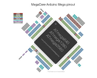
Best pictures are from the MCUdude's cores: https://github.com/MCUdude

ATtiny13: https://github.com/MCUdude/MicroCore


ATmega328 variants: https://github.com/MCUdude/MiniCore

ATmega8535 variants: https://github.com/MCUdude/MightyCore

ATmega640 variants: https://github.com/MCUdude/MegaCore


Thursday, May 29, 2014

4 * 7 segments

Pins:
1Segment E
2Segment D
3Decimal point
4Segment C
5Segment G
6Digit 4
7Segment B
8Digit 3
9Digit 2
10Segment F
11Segment A
12Digit 1


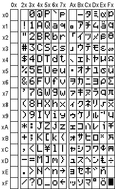
LCD screen HD44780

Charset: